Converting a single cab troop carrier to a Crewcab:
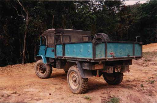
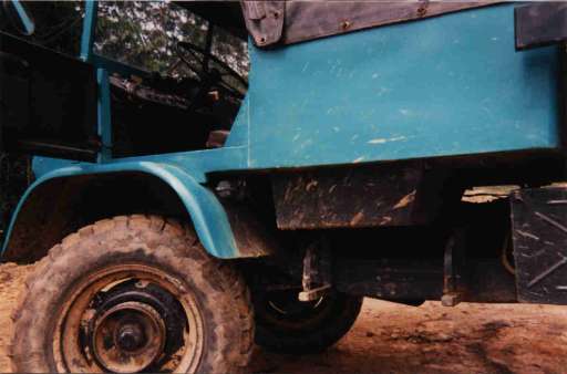
The first thing I did is to remove all the boxes fixed to the wooden floor of the flatbed. Then I removed the whole woodplanks. I also removed the 3 sidewalls.
Now the procedure is: Mark (well centered and parallel) 80 cm between the two transversals on which the flatbed rests on the chassis (as seen towards the cabin). One side (right) is fixed, the left side allows the chassis to flex under the flatbed. Cut it with a steel saw as long as it is possible (I found the material very "soft!") the rest can be cut with a little electric intermittent saw (how is the name??) with a sawblade for metal. Cut precisely withhout zig-zag or so, it's easier later then to weld the parts back together.
Now unbolt the back panel and put it backwards and position it (look for perfect alignment and 'square' the panel well to the flatbed). Tack weld the parts together with electrodes (3/32) and check again for good aligment in all directions of the frame and the backpanel. Now weld the parts together.
Now put one of the removed sidewalls on the shortened plainframe. Mark exactly where to cut and shorten the sidewall, be aware that the hinges have to correspond later with the hinges of the frame. Well measured? Then cut the piece out (80cm) to shorten the sidewall (electric saw). Tack weld the parts together, align them well, test that the sheet metal wall fits to the frame. I tack welded the metal sheet together until the gap was closed (very thin electrode) and then after re-checking - welded the metalprofile together. The other side is the same thing, pay attention that the hinges are reversed! Now clean all the weld seams and paint them with anticorrosion paint. Now decide if you want the floor of the bed to be the wood (30mm thick) you removed, or a 3 mm metal sheet (with anti-slide pattern).
The major steps of the cabin modification (404S to crewcab):
After finishing the flatbed and the sidewall modifications, now comes the moment to begin the work on the cab itself. Take out all the stuff (seats, doors etc). I shortened the flatbed 80 cm, and so I could enlarge the cabin by that size also. It is important to recheck (make a simple drawing, take notes) that the cab is inline with the flatbed and (important) with the frame, not inclined or displaced.
Do not use the floor (or a tool) as the horizontal level reference. It should be the frame (!). (If you find it easier to level over the truck, you have to first level the vehicle in all directions with accuracy !!!!!!! )
The top level for the upper edge is from the front of the doors (where the windshield hinges are next to it) over the doors rearward. I continued with the same slightly opening angle of the original cabin and so I got a 180 cm wide sitting area.
The new cab fits perfectly between the two boxes (storage) for the canvas arcs.
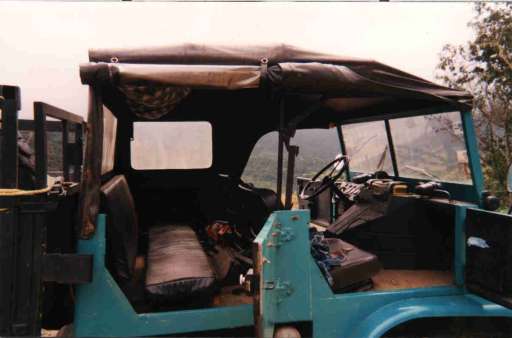
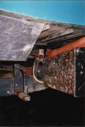
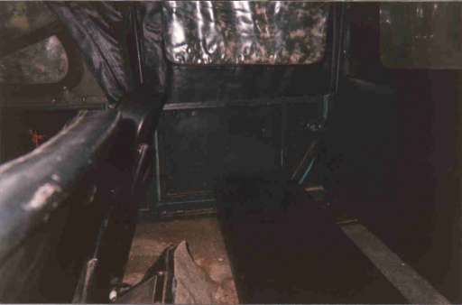
First I cut the backwall of the cab, just two inches behind the square tube where the supports for the cab canvas rest in a kind of pivot. Then I cut the floor straight through from side to side. The better and cleaner you cut, the easier the welding is later. The tools needed : Electric handsaw and standard handsaw for steel. The metal is surprisingly ‘soft’.
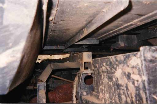
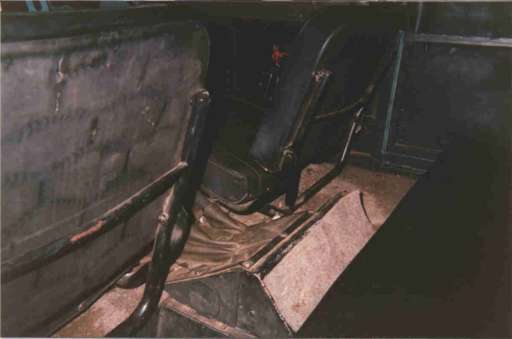
After removing the back wall, I built a transverse support with a pivot on the former front bases from the flatbed. (Take a look at the pics.) You have to level this transverse support well, because the floor frame of the new part of the enlarged cab will rest there. This design allows the cab to be well fixed and not to flex. The design is practical the same as the pivot at the front (under the MB star).
Now I continued "imitating" the original way of construction of the floor design, with 1 inch square tubes and 1" x 1" angles (3mm thick), you can perhaps see it in some of the pics.
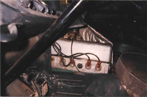
If you don’t want to relocate the spare tire, simply do not build the footwell box, and continue with the floor metal sheets on the same plane. When finishing the floor (E welding plus oxyacetylene gas welding) the construction of the side- and new backwall and the door begin. First weld the structure together, the same way the original design is. At this moment, I decided to move the cab with the now already aligned structure away from the Mog.
At this point, all the dimensions are fixed and you can work on the floor (away from the gas tanks).
So I could work (weld, paint) from all sides and from underneath (you and a helper can handle the cab on the floor over wooden beams without problems).
The door was also copied exactly and made as it was from a Mog. If you’re lucky , you insert an original door there if you can get one (or two if you want a 4 door cab) and save time! The hinges I used came from an FJ40, slightly shortened and adapted.
Then this "skeleton" was covered with a long metal sheet (sheet = 1.2 mm thick) from behind the driver’s door up to the opening of the new back door. The curves are realized the same way as the original (Take a look to your ‘old’ cab now).. Recheck often for the measurements, proportions and dimensions. The design of the tubes and arcs for the new cab canvas has the inspiration also from a FJ40 soft top.
The canvas was tailored together by a local upholstery shop (the household-sewing machine and my wife went on strike B^D ). If you level good, work with a normal grade of precision and be careful with the dimensions, with only copying the original design to the enlarged cab the work is not difficult. You need two things more: patience and time. The last work to do is to prepare the cab for the paint job.
Prime the whole piece, paint the parts now that are difficult to access later.
Then put the cab back on the frame and then paint. Now, reassemble your Mog.
Hopefuly, there are not too many parts and bolts left over. ‘8^)
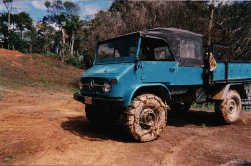
Now, are you ready for a 3 door Mog? Please refer for some details to the pics.
If somebody needs a better explanation of a detail, feel free to contact me.
|